- 您现在的位置:买卖IC网 > Sheet目录1214 > EVAL-ADE7880EBZ (Analog Devices Inc)BOARD EVAL FOR ADE7880
�� �
�
�Data� Sheet�
�POWER-UP� PROCEDURE�
�3.3V� –� 10%�
�2.0V� ±� 10%�
�0V�
�ADE7880�
�PSM0� READY�
�ADE7880�
�26ms�
�40ms�
�MICROPROCESSOR�
�MAKES� THE�
�ADE7880�
�POWERED� UP�
�POR� TIMER�
�TURNED� ON�
�ADE7880�
�ENTER� PSM3�
�MICROPROCESSOR�
�SETS� ADE7880�
�IN� PSM0�
�RSTDONE� CHOICE� BETWEEN�
�INTERRUPT� I� 2� C� AND� SPI�
�TRIGGERED�
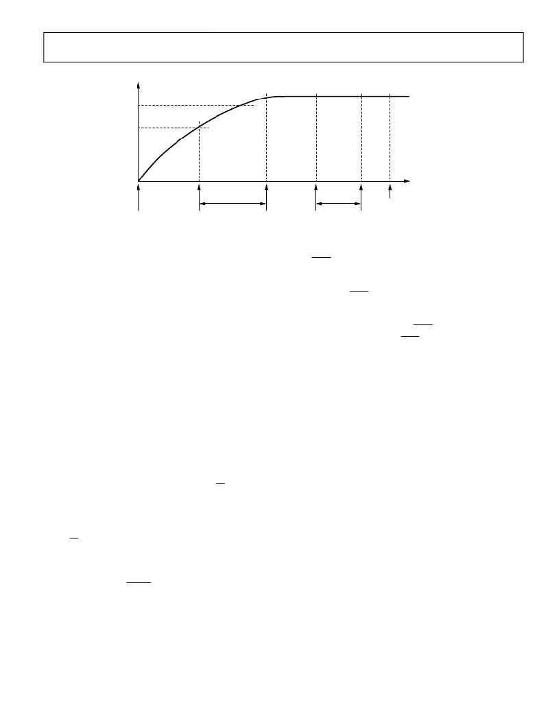
�Figure� 34.� Power-Up� Procedure�
�The� ADE7880� contains� an� on-chip� power� supply� monitor� that�
�supervises� the� power� supply� (VDD).� At� power-up,� until� VDD�
�reaches� 2� V� ±� 10%,� the� chip� is� in� an� inactive� state.� As� VDD�
�crosses� this� threshold,� the� power� supply� monitor� keeps� the� chip�
�in� this� inactive� state� for� an� additional� 26� ms,� allowing� VDD� to�
�achieve� 3.3� V� ?� 10%,� the� minimum� recommended� supply�
�voltage.� Because� the� PM0� and� PM1� pins� have� internal� pull-up�
�resistors� and� the� external� microprocessor� keeps� them� high,� the�
�ADE7880� always� powers� up� in� sleep� mode� (PSM3).� Then,� an�
�external� circuit� (that� is,� a� microprocessor)� sets� the� PM1� pin� to� a�
�low� level,� allowing� the� ADE7880� to� enter� normal� mode� (PSM0).�
�The� passage� from� PSM3� mode,� in� which� most� of� the� internal�
�circuitry� is� turned� off,� to� PSM0� mode,� in� which� all� functionality�
�is� enabled,� is� accomplished� in� less� than� 40� ms� (see� Figure� 34� for�
�details).�
�If� PSM0� mode� is� the� only� desired� power� mode,� the� PM1� pin�
�may� be� set� low� permanently,� using� a� direct� connection� to�
�ground.� The� PM0� pin� may� be� left� open� because� the� internal� pull�
�up� resistor� ensures� its� state� is� high.� At� power� up,� the� ADE7880�
�briefly� passes� through� PSM3� mode� and� then� enters� PSM0.�
�When� the� ADE7880� enters� PSM0� mode,� the� I� 2� C� port� is� the�
�active� serial� port.� If� the� SPI� port� is� used,� then� the� SS/HSA� pin�
�must� be� toggled� three� times,� high� to� low.� This� action� selects� the�
�SPI� port� for� further� use.� If� I� 2� C� is� the� active� serial� port,� Bit� 1�
�The� ADE7880� signals� the� end� of� the� transition� period� by� triggering�
�the� IRQ1� interrupt� pin� low� and� setting� Bit� 15� (RSTDONE)� in�
�the� STATUS1� register� to� 1.� This� bit� is� 0� during� the� transition�
�period� and� becomes� 1� when� the� transition� ends.� The� status� bit� is�
�cleared� and� the� IRQ1� pin� is� returned� high� by� writing� the� STATUS1�
�register� with� the� corresponding� bit� set� to� 1.� Because� the� RSTDONE�
�is� an� unmaskable� interrupt,� Bit� 15� (RSTDONE)� in� the� STATUS1�
�register� must� be� cancelled� for� the� IRQ1� pin� to� return� high.� It� is�
�recommended� to� wait� until� the� IRQ1� pin� goes� low� before� accessing�
�the� STATUS1� register� to� test� the� state� of� the� RSTDONE� bit.� At�
�this� point,� as� a� good� programming� practice,� it� is� also� recommended�
�to� cancel� all� other� status� flags� in� the� STATUS1� and� STATUS0�
�registers� by� writing� the� corresponding� bits� with� 1.�
�Initially,� the� DSP� is� in� idle� mode,� which� means� it� does� not�
�execute� any� instruction.� This� is� the� moment� to� initialize� all�
�ADE7880� registers.� The� last� register� in� the� queue� must� be�
�written� three� times� to� ensure� the� register� has� been� initialized.�
�Then� write� 0x0001� into� the� Run� register� to� start� the� DSP� (see�
�the� Digital� Signal� Processor� section� for� details� on� the� Run�
�register).�
�If� the� supply� voltage,� VDD,� drops� lower� than� 2� V� ±� 10%,�
�the� ADE7880� enters� an� inactive� state,� which� means� that� no�
�measurements� or� computations� are� executed.�
�(I2C_LOCK)� of� the� CONFIG2� register� must� be� set� to� 1� to� lock�
�it� in.� From� this� moment,� the� ADE7880� ignores� spurious� toggling�
�of� the� SS/HSA� pin,� and� an� eventual� switch� to� use� the� SPI� port� is�
�no� longer� possible.� Likewise,� if� SPI� is� the� active� serial� port,� any�
�write� to� the� CONFIG2� register� locks� the� port,� at� which� time� a�
�switch� to� use� the� I� 2� C� port� is� no� longer� possible.� Only� a� power-�
�down� or� by� setting� the� RESET� pin� low� can� the� ADE7880� be�
�reset� to� use� the� I� 2� C� port.� Once� locked,� the� serial� port� choice� is�
�maintained� when� the� ADE7880� changes� PSMx� power� modes.�
�Immediately� after� entering� PSM0,� the� ADE7880� sets� all� registers�
�to� their� default� values,� including� the� CONFIG2� and� LPOILVL�
�registers.�
�Rev.� A� |� Page� 23� of� 104�
�发布紧急采购,3分钟左右您将得到回复。
相关PDF资料
EVAL-ADE7953EBZ
BOARD EVAL FOR ADE7953
EVAL-ADF4002EBZ1
BOARD EVAL FOR ADF4002
EVAL-ADG788EBZ
BOARD EVALUATION FOR ADG788
EVAL-ADM1021AEB
BOARD EVAL FOR ADM1021
EVAL-ADM1023EB
BOARD EVAL FOR ADM1023
EVAL-ADM1031EB
BOARD EVAL FOR ADM1031
EVAL-ADM1062TQEBZ
BOARD EVALUATION FOR ADM1062TQ
EVAL-ADM1075CEBZ
BOARD EVAL FOR ADM1075
相关代理商/技术参数
EVAL-ADE7880EBZ
制造商:Analog Devices 功能描述:ADE7880, ENERGY METER, 3 PH, SPI, I2C, E
EVAL-ADE7913EBZ
制造商:AD 制造商全称:Analog Devices 功能描述:3-Channel, Isolated, Sigma-Delta ADC with SPI
EVAL-ADE7953EBZ
功能描述:BOARD EVAL FOR ADE7953 RoHS:是 类别:编程器,开发系统 >> 评估演示板和套件 系列:- 标准包装:1 系列:PSoC® 主要目的:电源管理,热管理 嵌入式:- 已用 IC / 零件:- 主要属性:- 次要属性:- 已供物品:板,CD,电源
EVAL-ADF4001EBZ2
制造商:Analog Devices 功能描述:Evaluation Board For Pll Frequency Synthesizer 制造商:Analog Devices 功能描述:ADF4001 PLL SYNTHESIZER EVAL BOARD
EVAL-ADF4002EB1
制造商:Analog Devices 功能描述:EVAL BOARD - Bulk
EVAL-ADF4002EBZ1
功能描述:BOARD EVAL FOR ADF4002 RoHS:是 类别:编程器,开发系统 >> 评估演示板和套件 系列:- 产品培训模块:Obsolescence Mitigation Program 标准包装:1 系列:- 主要目的:电源管理,电池充电器 嵌入式:否 已用 IC / 零件:MAX8903A 主要属性:1 芯锂离子电池 次要属性:状态 LED 已供物品:板
EVAL-ADF4007EBZ1
功能描述:BOARD EVALUATION FOR ADF4007EB1 RoHS:是 类别:编程器,开发系统 >> 评估演示板和套件 系列:- 标准包装:1 系列:PSoC® 主要目的:电源管理,热管理 嵌入式:- 已用 IC / 零件:- 主要属性:- 次要属性:- 已供物品:板,CD,电源
EVAL-ADF4106EB1
制造商:Analog Devices 功能描述:PLL, Frequency Synthesizer